
Wing Design
Overview
I was part of a team that designed and constructed a top-performing model airplane wing using balsa wood, epoxy, and MonoKote for my advanced strength of materials course. Each team started with an identical solid wing base model and our challenge was to modify it to remain intact the longest in a wind tunnel torsion test up to the maximum speed of 90MPH while also being as light as possible.
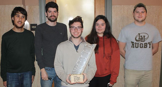
Picture: Our Team and Our Final Wing Before the Test
Finite Element Analysis
In the project we used finite element analysis (FEA) in SolidWorks to test our model wing concepts. We went through several iterations as we developed our wing from the initially provided solid wing model to our final design: a d-box with vertical rib deflection. With this design we took advantage of the benefits of a d-box structure without the typical weight associated with such a model to produce the minimum sheer and torsion. This resulted in a minimal increase in angle of twist and a large reduction in weight.
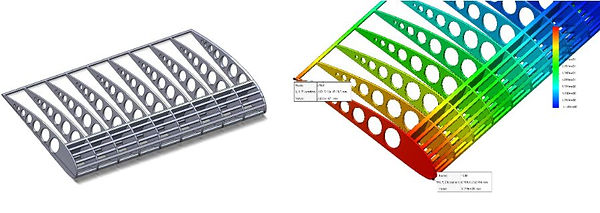
Picture: Our SolidWorks Model and FEA Results of the D-box with Vertical Ribs Deflection
Construction
First, we laser cut the ribs for our wing. We went with notched ribs so we could have multiple unbroken beams span the full length and avoid joints in the beams that might be locations for stress concentrations. Though we initially designed the wing with even rib spacing, we eventually decided to move to exponential spacing because a loaded and cantilevered beam will experience the maximum bending moment at the point at which it is mounted. As a result, reinforcement is needed closest to the mounting point. We put the wing together with epoxy and attached carbon fiber to the wing’s underside to help resist upward bending. After that, we added MonoKote film to make a scratch-resistant more aerodynamic surface and added the wing to the testing block with more epoxy.

Picture: Final Wing Model
Testing and Final Thoughts
Our wing withstood the maximum wind speed of 90 MPH and held there for 20 seconds. That test result in combination with our extremely light 28.24g wing made our wing a top performer. Through the project I learned invaluable design and project development skills as well as a better understanding of team dynamics and efficiency. For example, I discovered, it is crucial that every member add their own strengths while accommodating others’ input. While I conceptualized the overall design and crafting of the wing, others confirmed our finite element analysis or precisely connected the wings’ parts. Overall, this project was a great experience with FEA, torsional analysis, and engineering design.
